28+ block diagram control system
Simplifying block diagrams. Performed by each component in control engineering we commonly use a diagram called the Block Diagram.
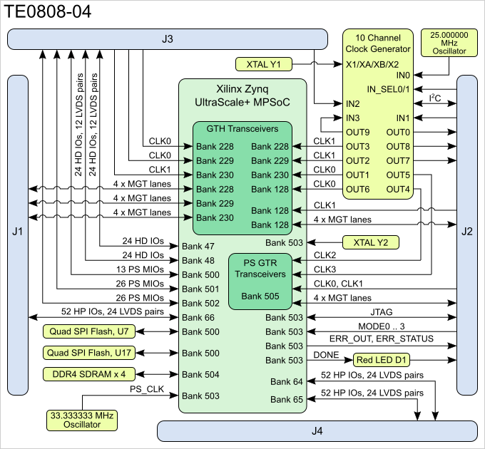
Confluence Mobile Trenz Electronic Wiki
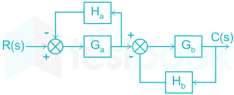
Rs Gs Gs Cs FIGURE 728.

. Any system can be described by a set of differential equations or it can be represented by the schematic diagram that contains all the components and their. Block diagram of a closed-loop system with a feedback element. A block diagram of a system is a pictorial representation of the function.
Block diagrams in control systems simplify the way that we approach systems and are perhaps the epitome of visualizing how a system interacts. Start at the OL poles end at the OL zeros or infinity. Problem 3 Block Diagram Reduction A block diagram of a control system is shown in Figure 728 below.
Y s G s X s Similarly block for each element of control. Functional Software Electrical etc. Ad Templates Tools To Make Block Diagrams.
These notes detail some techniques for. Block Diagram Reduction Figure 1. The output Y s is the product of input X s and transfer function G s of the block and is given by equation.
Root Locus Rules for plotting root loci Get the characteristic equation in the following form. The figure below shows the basic block diagram of the closed-loop. Use Rule 2 for blocks G 3 and G 4.
Use Createlys easy online diagram editor to edit this diagram collaborate with others and export results to multiple. The modified block diagram is. Step 1 Use Rule 1 for blocks G 1 and G 2.
Let us simplify reduce this block diagram using the block diagram reduction rules. BLOCK DIAGRAM SIMPLIFICATIONS Figure 5. Block Diagram Control System.
The types of the control system are. Single block diagram representation. A basic block diagram of the control system can be illustrated as.
Simplifying block diagrams Dynamics and Control with Jupyter Notebooks 001 documentation. A block diagram representation in which there is only one forward and feedback block along with a single summing point and take-off point is the simplest form of closed-loop control system. When we want to apply a different input signal to the same block then the resultant input signal is the summation of all the inputsThe summation of an input signal is.
Block Diagram in control systems.
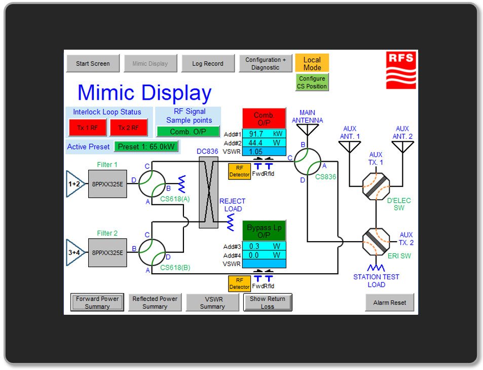
Msc Monitoring System Controller Rfs Radio Frequency Systems Your Global Rf Partner
Circuit Diagram For Temperature Controlled System Control System Temperature Control System

Confluence Mobile Trenz Electronic Wiki

Confluence Mobile Trenz Electronic Wiki
Solved Calculate The Transfer Function Of The Following System

Block Diagram Of Closed Loop Control System System Control System Transfer Function
Solved Find The Error Transfer Function E S R S Of The System Whose Block Diagram Is Given What Should K Be For The Steady State Error To Be Course Hero
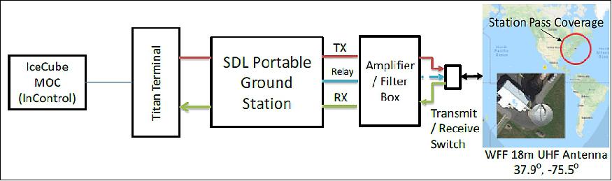
Icecube
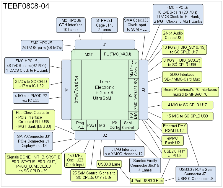
Confluence Mobile Trenz Electronic Wiki
![]()
Transmission Control Protocol Tcp Processing For A Listening Socket Download Scientific Diagram

Block Diagram Reduction Problem Solving Block Diagram Flow Chart
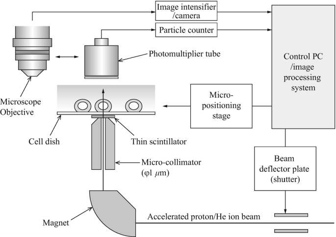
Experiments Of Local Irradiation Of Cells With Heavy Ion Microbeams Springerlink
Icecube
Solved Find The Error Transfer Function E S R S Of The System Whose Block Diagram Is Given What Should K Be For The Steady State Error To Be Course Hero
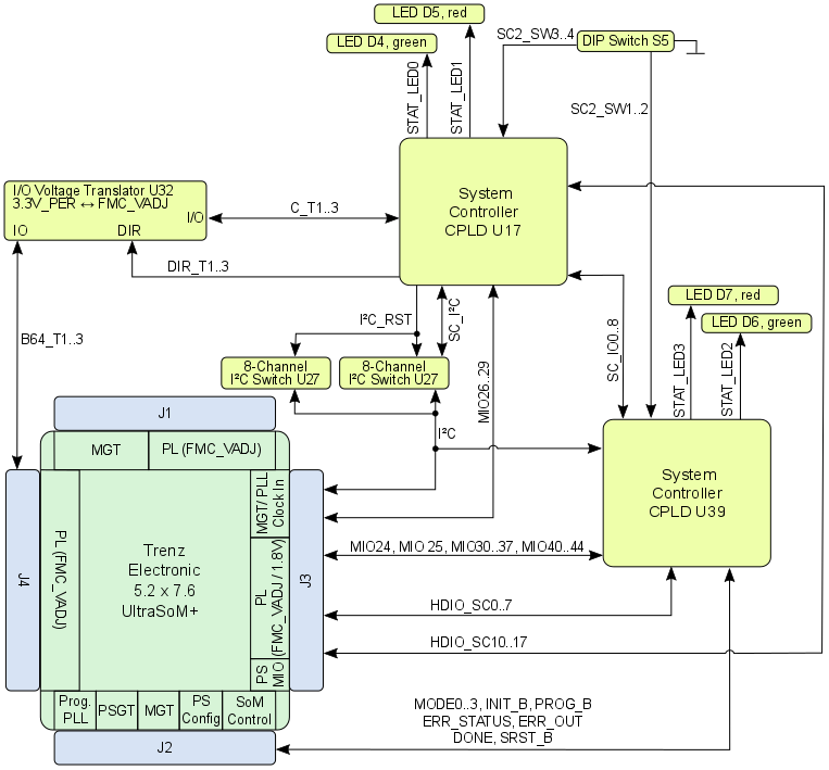
Confluence Mobile Trenz Electronic Wiki

Feedback Control Systems Block Diagram Engineering Student Chemical Engineering

Block Diagram For Open Loop Control System Control System System Control